Documentation
Original schematics, firmware source code, hardware photos, and technical reference for the 1991 HACKTIC Demon Dialer.
Schematic
The original schematic (v1.00) shows the complete circuit: MC68HC05C8 CPU, 4×3 keypad matrix on PORTB/PORTD, 7-bit R-2R DAC ladder on PORTC for audio output, and RS-232 serial interface via the on-chip SCI.
Hardware
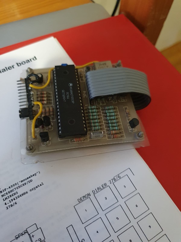
Original Demon Dialer v1.10
The original HACKTIC-produced unit with MC68HC05C8 one-time-programmable CPU. The PCB measures approximately 55×35mm and connects to a standard 4×3 keypad module.
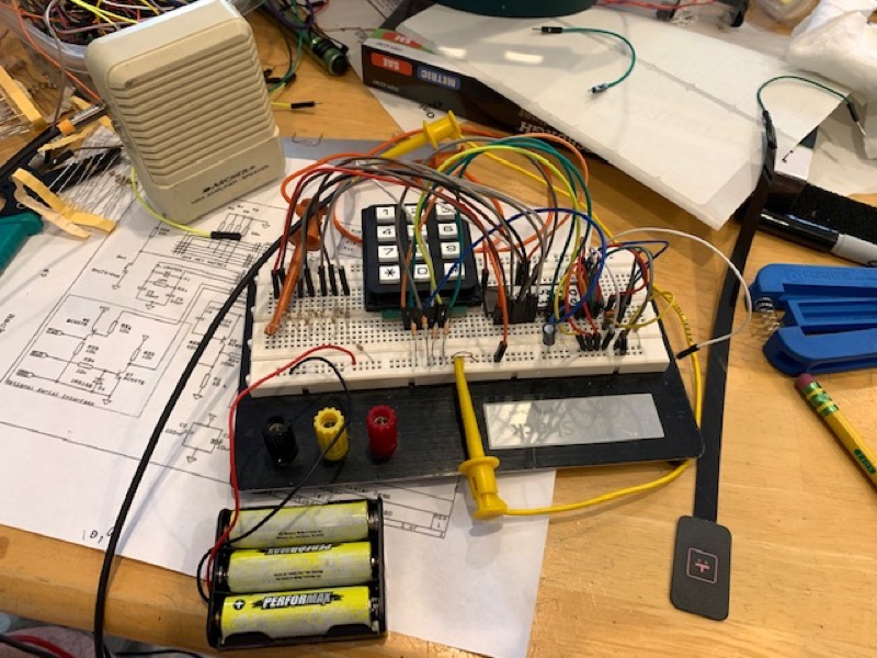
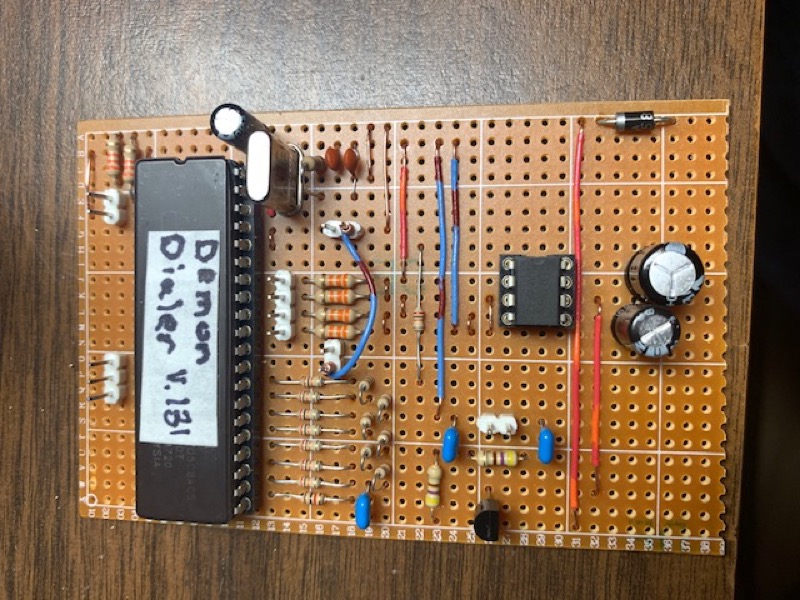
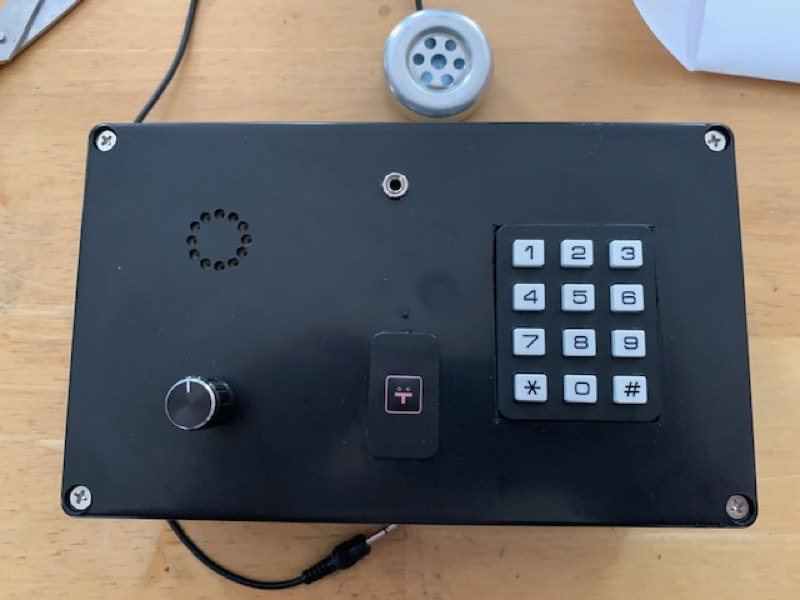
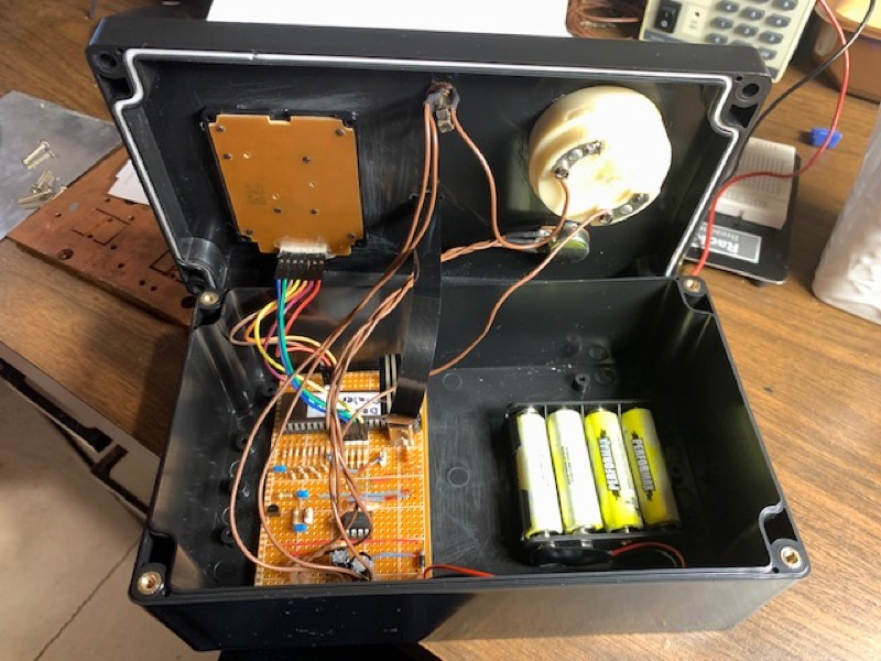
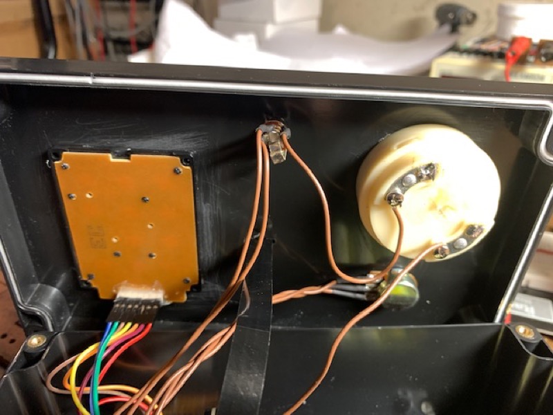
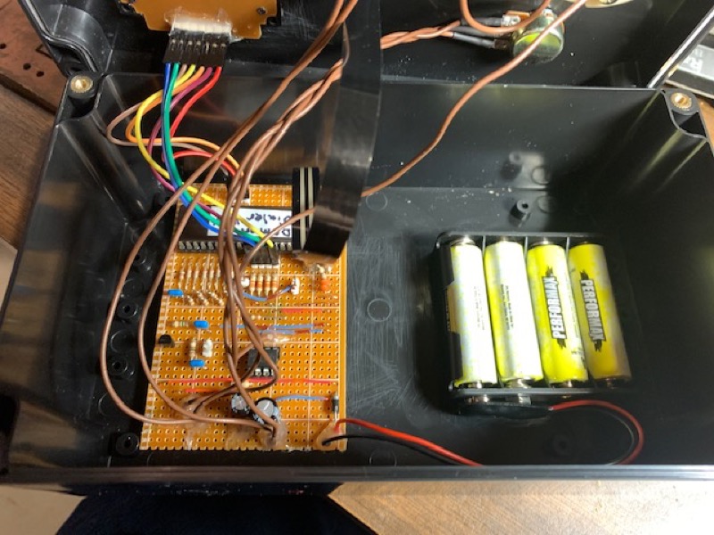
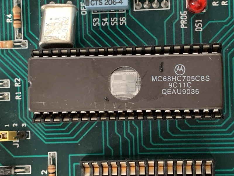
Don Froula's Build
Don Froula recreated the Demon Dialer using the UV-erasable MC68HC705C8S variant, allowing firmware development and debugging. His build progressed from breadboard prototype to finished perfboard unit.
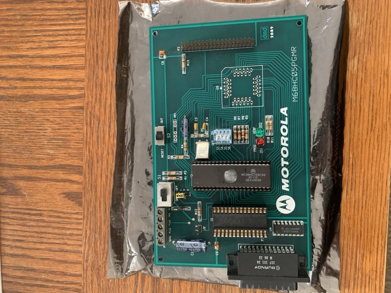
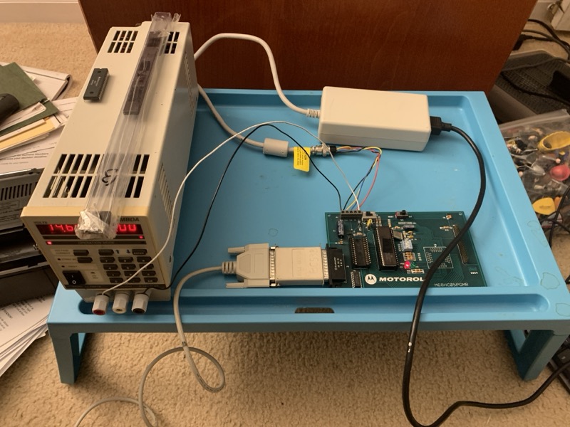
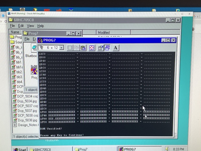
Programming Setup
Programming the MC68HC705C8S required a dedicated programmer board and DOS/Windows 95 software to burn the firmware onto the UV-erasable chip.
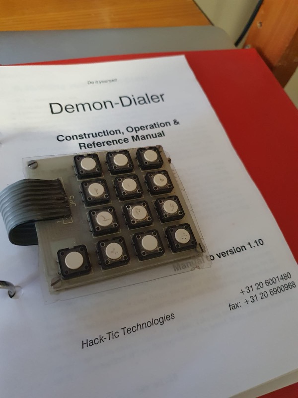
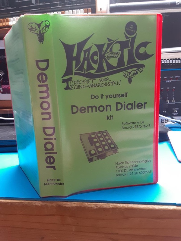
Original Packaging

Firmware Source Code
The complete firmware is 3,991 lines of Motorola 68HC05 assembly (demon131.asm, v1.31). Below are key excerpts showing the tone generation engine and frequency tables.
Memory Map & Variables
Frequency Table
DTMF Tone Data Table
Tone Generation Engine
Tone Reference
DTMF Frequencies
| 1209 Hz | 1336 Hz | 1477 Hz | 1633 Hz | |
|---|---|---|---|---|
| 697 Hz | 1 | 2 | 3 | A |
| 770 Hz | 4 | 5 | 6 | B |
| 852 Hz | 7 | 8 | 9 | C |
| 941 Hz | * | 0 | # | D |
MF (Blue Box) Frequencies
| Digit | Frequency 1 | Frequency 2 |
|---|---|---|
| 1 | 700 Hz | 900 Hz |
| 2 | 700 Hz | 1100 Hz |
| 3 | 900 Hz | 1100 Hz |
| 4 | 700 Hz | 1300 Hz |
| 5 | 900 Hz | 1300 Hz |
| 6 | 1100 Hz | 1300 Hz |
| 7 | 700 Hz | 1500 Hz |
| 8 | 900 Hz | 1500 Hz |
| 9 | 1100 Hz | 1500 Hz |
| 0 | 1300 Hz | 1500 Hz |
| KP | 1100 Hz | 1700 Hz |
| KP2 | 1300 Hz | 1700 Hz |
| ST | 1500 Hz | 1700 Hz |
| 2600 | 2600 Hz single tone | |
Red Box Coin Tones
| Coin | ACTS | Pattern |
|---|---|---|
| 5¢ (Nickel) | 1700 + 2200 Hz | 1 × 66ms burst |
| 10¢ (Dime) | 1700 + 2200 Hz | 2 × 66ms bursts, 66ms gap |
| 25¢ (Quarter) | 1700 + 2200 Hz | 5 × 33ms bursts, 33ms gap |
External Resources
Hacktic Magazine #14/15 (1991) — hacktic.nl/magazine/1448.htm
Project MF — Originally created by Phiber Optik (Mark Abene) as a living simulation of a blueboxable phone line: projectmf.com (archived)